Adding an internal speaker to the Pocket CHIP
The Pocket CHIP doesn’t come with internal speakers. It has the GPIO pins for audio, but nothing is hooked up. On the CHIP itself there is a 3.5mm audio jack for connecting headphones, and you can pair a Bluetooth speaker.
On the old NTC blog there was a post back in 2016 about adding an internal speaker using a fairly inexpensive PAM8403 amplifier and a speaker. You can find a mirror of the old post from the NTC blog on archive.org

Adding an internal speaker
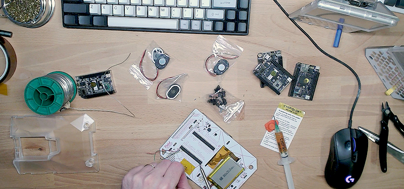
You need the following parts:
- PAM8403 amplifier board
- 23mm 8ohm speaker
- 30AWG wire
- Kapton tape
- Soldering iron (and accoutrements)
And this is the process:
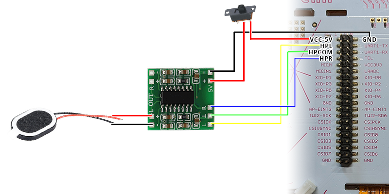
- Position the amp to the left of the CHIP on the back of the Pocket CHIP mainboard
- Solder the GND pad on Pocket CHIP to the – pad near the 5V pad on the amplifier.
- Solder the VCC-5V pad on Pocket CHIP to the 5V + pad on the amplifier.
- Solder the Pocket CHIP HPL pad to the amplifier’s L pin.
- Solder the Pocket CHIP HPCOM pad to the ⊥ pin.
- Solder the Pocket CHIP HPR pad to the amp’s R pin.
- Solder the speaker -/+ wires to either the L-/L+ or R-/R+ pads on the amplifier
- Dry test fit to make sure the back will fit on the Pocket CHIP. without any obstruction
- Glue everything in place, being careful of shorts

You can attach two speakers to the amplifier, but one will probably be enough for the bleeps and blerps in Pico-8 games.
To disable the speaker output, you have a couple of options:
- In software, use alsamixer and toggle mute.
- In hardware, add an inline switch on the VCC-5V line to switch the amplifier off when you don’t need to use it, and save some battery.
Adding an inline power switch
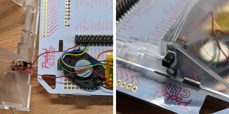
Adding the switch is simple. You just need to splice a switch in on the VCC-5v line, and find somewhere in the Pocket CHIP to mount it.


- Cut or de-solder the VCC-5v line
- Solder the center and one of the external legs of the switch
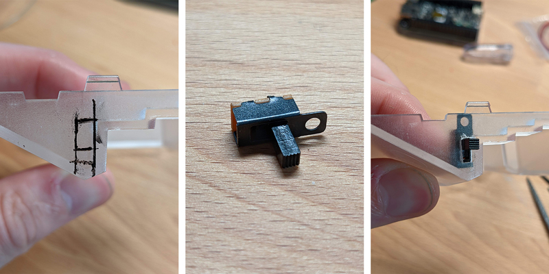
- Decide where you would like to install the switch and mark the case
- Drill a small pilot hole. I used a 3mm bit here. Go slowly and take your time.
- Tidy and shape the hole using hand tools. I have a selection of small hand files that worked excellently. I used a 2mm square file and a 4mm flat file. As with the drilling, go slowly and take your time.
- Ensure everything fits
- Glue the switch in place. I had to trim one of the mounting holes from the switch to make it fit where I wanted. Be careful when applying the glue. The Pocket CHIP case is see-through so you don’t want to make a massive mess and you don’t want to get glue inside the switch.
- Put the Pocket CHIP back together.

This post is also available in plain text
GitHub API rate limit exceeded. Comments available again at